 Fasteners have been around for a long time and there continues to be new ways of driving fasteners into the materials they are intended to hold together. In recent years there has been a push from the medical industry on bone screw applications with hex shapes, Torx ® or Hex lobular, square and spline drives. Materials such as titanium, Cobalt, and high-temperature alloys have made the job of putting a shape in the head of a screw much more difficult. Fasteners have been around for a long time and there continues to be new ways of driving fasteners into the materials they are intended to hold together. In recent years there has been a push from the medical industry on bone screw applications with hex shapes, Torx ® or Hex lobular, square and spline drives. Materials such as titanium, Cobalt, and high-temperature alloys have made the job of putting a shape in the head of a screw much more difficult.
Rotary Broaching, also known as Wobble Broaching, has been one method used to obtain these various shapes. Well known and used for years on automatic lathes, Rotary Broaching has become the method of choice on Swiss Type machines, CNC lathes and Machining Centers because it eliminates a secondary operation.
How Rotary Broaching Works - The basic principle of Rotary Broaching is relatively simple. Internal and external polygonal profiles are single point shaped rather than form punching. The operation is performed in only a few seconds while the spindle is rotating. PCM Willen reports that the cutting action requires 80% less force than form punching when the optimum feed rate is used. The reduced stress increases too life and lowers machine maintenance cost over time.
On a machining center, the broach holder revolves in the spindle while the tool and part is stationary. It is the opposite on a lathe where the part rotates synchronously with the tool while the holder is held in an ID position. The operation takes only seconds and can eliminate a secondary operation so the part can be produced complete in one setup.
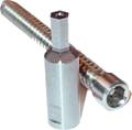
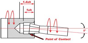
The broaching holder serves two functions; it holds the broach tool in a free spinning bearing and places it at a 1° angle relative to the centerline of the work piece. The face of the broach tool is the apex of the 1° and is located on the same centerline as the work piece. Built into the tool is a 1-1/2° clearance angle. As the tool comes into contact with the spinning part, it begins to rotate synchronously like a gear due to friction. As the tool is thrust into the predrilled hole the wobble effect causes the leading edge to rotate in and out of the cut like a cam. As the tool advances forward in a wobbling motion each tooth cuts the same groove with a scalloping effect as is rotates in and out of the leading point. Similar to a wobbling coin, only one point is touching at any given time, greatly reducing the amount of force needed to form the shape.
|
What Materials Can Be Broached According to PCM Willen, almost all free-cutting materials can be successfully broached up to 850N/mm 2 tensile strength without greatly reducing tool life. Materials such as heat treated steels and non-free cutting stainless will reduce tool life depending on hardness.
Preparing To Broach A Hole - The hole should first be prepared with a 60°- 90° chamfer slightly bigger than the largest dimension of the broach tool. This ensures easy starting of the broach by guiding the tool in.
Drilling The Hole - For internal broaching, the hole should be drilled approximately 1 % bigger than the diameter across the flats of a hex shape. This percentage can be reduced in free cutting material and increased as machinability decreases. In mild steel we recommend the following tolerances:
.059-.118 = .001- .002 |
.118-.236 = .0015-.0035 |
.236-.394 = .0025-.005 |
.394-.630 = .004-.008 |
> .630 = .006-.012 |
Drill the hole as deep as possible to leave room for chip accumulation. A depth of 1.3 to 1.5 times the length of the profile is recommended. If the chips need to be removed, re-drill the hole with a slightly smaller drill size.
Drill Radius Not Allowed - Many medical and aerospace applications do not allow for a drill radius along the broached walls of the part. When exact concentricity is required, c'bore, drill and pre-bore the hole which will keep the broach concentric when it enters the hole. As the broach plunges into a tight fitting hole there is no room for air or coolant to escape. The hydraulic pressure being generated is enough force that something must give. Many times the part or tool will push back however the tool or machine can also be damaged. In this case a pressure relief vent in the broach is recommended allowing oil and air to escape.
Recommended Speed - The basic principle of the 1° offset allows high speed application from 1500 up to 3000 rpm. Surface footage has very little effect on cutting action or the tool life. The cutting edges of the broach tend to dig in to the face of the part as the tool comes in to contact with the rotating material. At higher speeds this dig mark will become more pronounced and tool life will suffer. For best results start the broach operation at a slow rotation and then increase the speed when it is in full contact. Reversing the spindle rotation half way into the part can reduce spiraling.
Feed Rate - The feed choice mainly depends on the material characteristics. In a mild-steel, we recommend .0012 -.0024 per revolution. If the machine thrust force is sufficient, the feed can be doubled even tripled as machinability increases. In most cases the maximum feed rate should not exceed .03 x the profile diameter. A slower feed rate will produce an improved finish with finer lines along the sidewalls of the broached hole. By increasing the feed rate the cutting cycle will be faster but the broaching lines will be more pronounced leaving a coarse finish.
Coolant Water soluble coolant or cutting oil are both sufficient for Rotary Broaching. The increased size of the pre-drilled hole usually provides ample space for coolant to leak out as the broach tool plunges in. In a tight fitting hole a pressure relief vent should be added to the broach tool.
Centering The Broach To obtain a quality broached hole and optimize too life, the tool should be on center with the work piece within .0008 or less. Poor centering will result in the shape being eccentricity with the bore, spiraling, increased dig marks at the start, over sized holes and reduced tool life. |