Premium Rotary Broaching Products
rotary broaching tools for CNC swiss, turning centers and lathes swiss broaching holders, no center indicating heavy duty rotary broach holders for CNC machines precision rotary broach tools, hex and torx profiles
tooling and accessories for CNC swiss machines rotary broaching tech support and speeds feeds how to rotary broach in a lathe external broaching applications, spline broaching
Rotary Broaching Technical Support
Basic Cutting Principle - The tool is held at a 1° angle relative to the part centerline and has a 1° 30'' clearance angle built in. The face of the broach tool is the pivot of the 1° angle and is placed on centerline with the part.  As the tool comes in contact with the part, friction drives the broach to rotate synchronously. The cutting edge is kept on center and the rest of the tool oscillates around the part centerline with a wobble effect.  With the faces of the tool and part at a relative 1° angle, only the leading point of the tool is cutting and not the entire profile. The wobble effect moves the leading edge to rotate in and out of the cut like a cam. It shears the shape into the part with a scalloping effect as it advances forward. This reduces the required thrust force up to 80% when it is at the optimum feed
basic rotary broaching principle
Precision Rotary Broaching
Coolant - Usual coolant or cutting oil can be used, however it is typically unneccessary as rotary broaching produces little heat. Also, excessive coolant in the broach pilot hole can result in hydraulic lockup during broaching. Vented broaches can solve this problem if it encountered.
Broach Preparation - A 60° or 90° chamfer, slightly bigger than the largest dimension of the broach, is essential for and easy start of the broach. When exact concentricity is required, counter bore the hole at the same size as the measured profile across corners, boring approximately .020” deep will provide the best results.
Drilling The Hole - For internal broaching, the hole should be drilled approx. 1 % bigger than the diameter across the flats of a hex shape.  This percentage can be reduced in free cutting material and increased as machinability decreases. In mild steel we recommend the following tolerances:

.059-.118 = .001- .002

.118-.236 = .0015-.0035

.236-.394 = .0025-.005

.394-.630 = .004-.008

> .630 = .006-.012

Drill the hole as deep as possible to leave room for chip accumulation. We recommend a depth of 1.3 to 1.5 times the length of the profile. If there is insufficient room for chips, damage will occur to the cutting tools and holder.
**IMPORTANT** When a drill radius is not allowed along the broached walls of the part, tool life and bearing life will be reduced. When exact concentricity is required, c'bore, drill and pre-bore the hole which will keep the broach concentric when it enters the hole.  With such a tight fit push back may result as the broach becomes a hydraulic ram. This pressure can be relieved with a vent hole supplied in the broach tool.
Centering The Broach - Nothing is more important than having the cutter centered as close as possible to the center of the work piece. Improper center setting will cause an uneven hole configuration, oversize holes and spiraling.  The maximum eccentricity should not exceed .0008” To simplify setup on more accurate Swiss Type and Gang Machines, use our (on-center) 2100 Series holders.  For easier setting on conventional CNC and other machines, use our gages 6189 or 6199 with the adjustable type broaching heads.
An excellent place to start with feed rate is by using the following formula: .016 x h = Inches / Revolution, where 'h' is equal to the size of the hex you are attempting to broach.
Broach Sharpening – An external or internal broach tool can usually be sharpened one or two times if the tools are in reasonable condition. Only the front face will be re-sharpened with a cutting angle from 4 to 8°.
Broach Setup For 2100 & 2160 Series Swiss Type Rotary Broach Holders

Setup of Swiss Type broach holders:

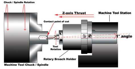
The 2100 and 2160 Swiss type holders do not require centering with an indicator.  These heads are designed for machines with more accurate centering built into the machine. This would include Swiss Type CNC, Gang type, and small precision lathes, all of which are designed for small diameter precision turning.  It is not generally recommended to use the 2100 series broach head on conventional CNC turret type lathes due to the centering inaccuracy associated with these lathes.  With the 2100 series broach head it is essential to use the correct length broach.  The overall length of the broaching bit is 28mm +0,30 -0,0 and the shank diameter is 8mm with an h5 tolerance. Failure to use the correct length or to bottom out the broach will result in poor broach size, & quality.

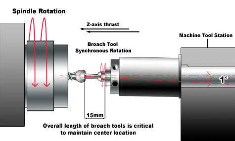
All 2110 Series Broaches are tightly controlled on the Overall Length Tolerance to ensure proper center location when used in Swiss-Type Rotary Broach Holders

swiss type broach holder setup
How to Setup an Adjustable Center Rotary Broach Tool Holder - 6180 & 6190 Series

Setup of Adjustable Style Broach Holders:

For machines like turret lathes, that can not place the tool accurately with the spindle centerline an adjustable broaching head should be used to compensate for center. With an adjustable head a gauge pin that is the same length as the broach is inserted into the head and the very tip is indicated on find center.

PCM broaching holders series 6180, 6190, 26200 and 26300 are delivered adjusted within .0006” for our standard tools with a 55mm +0.3 length.  When tools with different length are used, it is essential to re-adjust the exact centering position.  Experience has proven that turret bores are not in perfect alignment with the machine spindle after a certain working time.  When misalignment is over .002 of an inch it is necessary to re-adjust the turret positioning to avoid broaching difficulties especially on small sizes.

Adjusting Center On The Machine- Adjustment for center on the machine offers the advantage to correct misalignment between the machine spindle and the turret bore. With the gage pin (4) set to the proper “L”, set the broach head in the turret station (1) to be used for broaching. Set the indicator (5) on to the spindle chuck with a magnetic base. Place the indicator tip on to the end of the gage pin. Rotate the chuck so the indicator sweeps the diameter of the pin and adjust accordingly using the adjustment screws.

rotary broach holder setup

Adjusting Centering Off-Line- Set the indicator tip (5) on the gage pin (4) at the correct “L”. Rotate the holder on it's shank (2) in the preset fixture (1) to obtain a max. TIR of .0008”. (Notice the oscillation of the gage pin as it rotates with the holder)


Thank you for taking the time to visit our site. Please do not hesitate to call or email with rotary broaching application questions or if you need help deciding which tools are right for your job.

Hours of Operation: Mon - Fri    8:00AM  -  5:00PM Eastern Time

Genevieve Swiss Industries, Inc.
6 Old Stage Road
Westfield, MA 01085
Ph: (413) 562-4800
Fx: (413) 562-4802
EMAIL: Sales@genswiss.com
All Images and Content ©Genevieve Swiss Ind. Inc.